Tuesday, May 7, 2013

Senior Design Expo

The final presentation for Mechanical Engineering seniors is the Senior Design Expo.  On this day all senior projects are presented to judges from various positions in the Engineering community.  The team was ready to present our baking successes and final design to the Columbia Engineering faculty and students.  

Dough Boyz with Bake360

Judges were allowed to taste samples of pumpkin bread, chocolate bread, and soft pretzel that had been baked in the last few days.

Andrea presenting samples to Judges

While not required, a good way of presenting a summary of the senior design process, from concept to results, is via powerpoint poster.  This allows the judges to obtain a brief visual overview before talking to the group.


The team had a terrific time discussing the journey that was our senior design project with the various judges and letting them get a taste of the future of baking. 

Thursday, May 2, 2013

Testing Round 2: Soft Pretzels

After machining longer prongs, we decided to test again with a new type of dough. 

Soft pretzel dough is boiled in a mixture of baking soda and water prior to baking. This additional step gives it an extra firm structure and forms a slight crust. With this additional support, we hoped that a sufficient crust would form to support the inner portions of the dough as it finished baking. 

Thankfully, this proved to be true and we got our first fully cooked baked good! The total baking time for a 3" sphere of pretzel dough was about twice that of the expected time when cooking on a traditional baking sheet. This is likely because the baking is done almost entirely by convection rather than the conduction that occurs through a metal baking sheet. 

We achieved the desired shape and the 360° crust, but we also learned that there are many things to be altered to make the device more user friendly and improve the food quality. 

Because it is difficult to remove the prongs from the inner ring the dough was formed around the prongs rather than skewering it through a perfect sphere. This caused the imperfections in the dough seen below. We hope to alter the prong attachment to use set screws which will allow easier placement and removal of dough. 

While there are more improvements in the works, we were certainly happy to take a victory lap around the shop letting Mohammad and Ottman be our taste testers to thank them for all their help. 

Tuesday, April 30, 2013

Further Testing

After the mixed successes with biscuit dough, we decided that a major issue was that the rings were not rotating enough to negate the downward pull of gravity on the dough.  A few solutions were proposed, including using magnets to offset the rings if they reach a point of minimal energy.  This idea was discarded as the magnets would quickly lose their effectiveness in the oven environment.  In addition, the price and timeline for delivery would set the group outside of our limits.

Example of 'Gimbal Lock'


Another solution that the group discussed was weighting the rings such that there was an imbalance in the moment of inertia, which would hopefully offset the rings enough to prevent the 'gimbal lock' issue.  With just one weight, the device tended to have the weighted end near the bottom of the oven, with very little rotation of the inner ring.  This made the dough droop excessively.  Adding another weight 120 degrees away from the first provided the perfect offset that allowed the rings to rotate more fluidly.


Thursday, April 25, 2013

Initial Testing

First testing day!

We attempted to bake a buttermilk biscuit dough. This yeast-based dough has very little butter and is relatively dense compared to many other bread doughs. We attempted two configurations in this test, both of which were unsuccessful. The first test used all three prongs at a slow rotation speed. The dough stayed on the prongs for roughly 1 minute but as it began to heat up it became less viscous and fell off the prongs. Further attempts to reposition the dough on the prongs was unsuccessful.


The second test used a smaller amount of dough, first mounted on a single prong then pierced with the other two. This differed from the first attempt to mold the tough onto the prongs. Roughly 5 minutes into the rotation, the dough began to droop down away from the center and fell off:


We brainstormed many potential solutions and machined longer prongs for the inner ring so that the dough can be more supported through its baking. In addition we plan to thread these prongs and use nuts and washers to give extra support to the dough. While this increases the amount the metal is touching the dough, we believe it is necessary in order to complete the baking process. 


Wednesday, April 24, 2013

Final Assembly


Today we finished the mounting of the motor and fixed the gimbal lock issue. Essentially, we added a weight to one of the rods within the inner ring and decided to spin the device in a slow to ensure a random tumble. The motor box was mounted using wodden blocks and self tapping screws. A significant addition that can be seen is the white piece of Teflon used as a heat resistant coupler. This will be used to prevent heat transfer to the motor:

Mounted Motor Box
Top View of Motor Box

With the assistance of Ottman Tertuliano, the triangle frames were TIG welded to the baking sheet along with two handles to enable easy placement in the oven:


We added a cylindrical weight to one of the prongs in order to offset the effects of gimbal lock. With the weight in place, the inner ring rotates more as the middle ring attempts to fall into its equilibrium position perpendicular to the outermost ring. This added rotation of the inner ring maintains the desired motion of the device. 

Added Weight to Inner Ring

Final Assembly of Device


Monday, April 15, 2013

Oven Door Puncture

Our team decided to drill the hole in the oven side that the drive shaft will feed through today. Under the supervision of Doug and Mohammed, we used a handheld drill to form the hole in the side of the oven:

Hole in Oven Prior to Cleaning
Testing the motion of the Bake<sup>360</sup>, we find complications with the middle and smallest ring as they appear to lock in a certain location quite often. Known as a gimbal lock, we aim to solve this problem through use of magnets, weights, or slowing the motion of the device down:


Placing the device in the oven with set blocks on the right and back, we have settled upon a desired location for the gyroscope within the oven:
Device Placement
Shaft to Coupler Placement
Drive Shaft Through Other Side
Setting Block

Friday, April 12, 2013

Coupler/Drive Shaft

Due to complications with a purchase order, we decided to manufacture our own coupler and drive shaft with steel found around the shop. With the lathe, we produced the coupler that will be in direct contact with the outer ring and the motor drive shaft on respective ends:

Motor side of coupler
Coupler
Device side of coupler
In addition, we selected a steel rod to machine as the drive shaft. Before we can machine it, we need to determine the final positioning in the oven to determine its length.:

Drive Shaft Selected for Machining

Wednesday, April 10, 2013

Assembly Completion

As of last night, our group was able to assemble the rings after completing final machining with the help of Bob:


Tuesday, April 9, 2013

Pins/Rods/Motor Completion

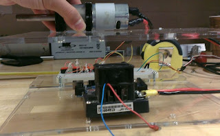
After changing a few designs for our motor, we assembled it. With the input of Mohamed, we decided to put "glove-like" material between the acrylic face and the oven wall  to prevent as much heat as possible from getting into the acrylic motor box. Our box will require two power sources, one for the motor and one for the Arduino:


Aiming to put the rods 120 degrees from each other in the inner ring, we threaded the ends of each of the three rods:


At the same time, we aim to machine the shafts on each of the rings today, 6 total, using the vertical machine. Given the large nature of the outer most ring, multiple supports were need to reduce the movement and vibrations associated with the cutting.We ran the tool at a feed setting of 5 and 1500 RPM:


As of 3:40 today, we were able to fully manufacture the outside ring and its spins effortlessly:


Monday, April 8, 2013

Motor Box Prototype

After reasoning out that a breadboard was unnecessary for the function of our device, we decided to to eliminate it completely, significantly reducing the size of the proposed motor box. Designing the motor with Creo, we saved the files in a cgm format to use the laser cutter:

Motor Box with the Left Panel Removed to Show Internal Components

Running the program for roughly 2 hours at 100% power, 1% speed, we produced a motor box entirely out of acrylic:


Sunday, April 7, 2013

Motor Box/Freeing Rings

Having taken measurements of the electrical components, our team used the laser cutter to ensure that the holes made for the components were aligned correctly. To avoid waste, we used the acrylic that was found in the dump/recycled area that was most likely to go unused the rest of the year:


We look to fine tune the motor box model tonight in order to have the electrical components in their proposed places in time for the technical review. 

In addition, we took a hacksaw again the the steel sheet and finished the freeing process of the rings, producing three individual ones:


Thursday, April 4, 2013

Freeing Rings/Motor Measurements

Continuing with the machining of the rings, we decided to take a hacksaw to the steel sheet:


This method was met with success as we had no trouble freeing the outside of the ring structure. 

We were also able to complete the wiring for our motor today. Upon successfully setting the device so that the motor speed would vary via a potentiometer, we decided that motor placement would be tackled next:


Seeing that the length of each of the components would be too long to create a single tiered motor box, we propose a two shelf system.We aim to produce a motor box that will have the electrical components at the top while the motor is at the bottom. In addition, we also look to design the box so that the motor can be easily be slid in and out of the oven opening. 

Wednesday, April 3, 2013

Day 2 Rings and Motor Set Up

Today we finished the machining of the rings. Shout out to Christie Taylor's group for allowing us to use their machining slot. The rings finished with little trouble until the very end, in which our tool broke. With no replacement tools ready at hand, we called it a day and removed the sheet of steel:


With the rings still not freed, Bob Stark suggested that we use a hacksaw at the appropriate places to finish the process. 

Tuesday, April 2, 2013

Ring Machining

Machining of the rings today out of of a half inch thick sheet of steel. We first cut out a piece of acrylic for the jig on the CNC machine:


During the machining, the support structures were tapped by Andrea and Dan:


In order to begin the machining of the rings, it was suggested that we drill and tap 4 holes into each of the three rings and attach them to the acrylic jig below.this ensures that he rings will not move during machining.


Machining would continue until roughly 7 PM, at which point, the first ring was finished and the inside of the second ring was in progress: